David Zientara

Adding Link Aggregation in OPNsense

Link aggregation (usually abbreviated as LAG) allows us to combine multiple ports in parallel, which accomplishes two goals:

  • It increases the amount of throughput; for example, if you have two trunk ports per switch, you will have more throughput than you would with a single port.
  • It provides some redundancy in case one or more ports go down

The LAGGS option does not refer to an interface. Rather, it refers to LAGG the FreeBSD link aggregation and link failover driver. Typically, trunk ports involve some form of link aggregation. With some switches, trunks have to be configured as pairs of ports.

There are two ways to add a new LAGG interface: at the console and within the web GUI. To add a new LAGG interface at the console, log into the console and do the following:

  • Enter 1 to enable interfaces.
  • When the console queries “Do you want to configure LAGGs now? [y/N]:”, enter ‘y’ and press [Enter].
  • The console will list all the LAGG-capable interfaces. Enter the LAGG member to aggregate (e.g. em0, em1, etc.), or nothing if you are finished.
  • At the next console prompt, enter the LAGG protocol (default: none, lacp, failover, loadbalance, roundrobin). These options are as follows: Protocol Description NONE Disables traffic, but does not disable the interface. LACP The Link Aggregation Control protocol, defined by IEEE 802.3ad. LACP provides a form of load balancing by automatically bundling together links. FAILOVER One port is designated as the active port; all other ports are used as failover ports. If the active port goes down, one of the failover ports becomes the new active port. FEC This protocol supports Cisco Fast EtherChannel, unlike most of the other options, it is a static setup. LOADBALANCE This protocol balances all outgoing traffic on the member ports. This is also a static setup. ROUNDROBIN Distributes outgoing traffic in a round robin fashion; in other words, in equal slices and in a circular pattern.
  • If LACP is selected, enter ‘y’ if you want to enable LACP fast timeout. If this is enabled, then one of the channels will time out after about 1 second. In the end, you must decide if 1 second is long enough, or if you should allow a few dropped packets so you won’t have to rebuild the LACP link.
  • The next prompt is whether you want to configure VLANs. Enter ‘y’ if you want to configure VLANs, or ‘N’ otherwise.
  • Finally, assign the interfaces for WAN, LAN, OPT1, and other interfaces.

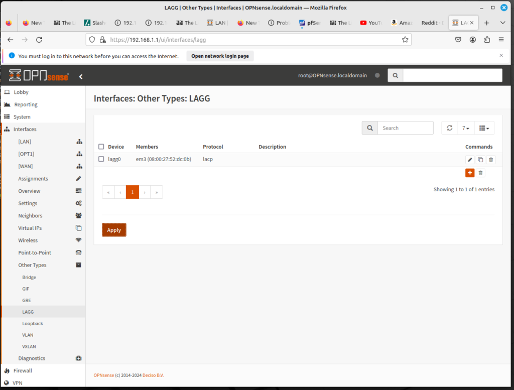
You can also add a LAGG interface in the web GUI. To add an interface, log into the web GUI and do the following:

  • On the left sidebar menu, click on Interfaces, Other Types, and LAGG.
  • Here you will see a table listing all the LAGG interfaces. Click on the plus (+) icon to add an interface.
  • In Parent, use the drop-down box to select the parent interface used for link aggregation.
  • In the Proto drop-down box, select the protocol. See above for a table with an explanation.
  • For the Fast timeout checkbox, select this option if you want a fast timeout (approximately 1 second). The costs and benefits of enabling this option are discussed above.
  • In the Use flowid drop-down box, select Yes (use the hash from the network card, if available), No (a hash is locally calculated), or Default (the value depends on the system tunable net.link.lagg.default_use_flowid). You may need to change this value if you are having a problem with flapping.
  • In the Hash Layer drop-down box, set the packet layers to hash for aggregation protocols which load balance. The options are options that correspond, respectively, to the data link, network, and transport layers:
    • Layer 2 (source/destination MAC address and optional VLAN number)
    • Layer 3 (source/destination IPv4/IPv6 address)
    • Layer 4 (source/destination port)
  • In the Use strict drop down box, select Yes to enable strict LAGG enforcement, No to disable enforcement, and Default to use the value from the system tunable net.link.lagg.default_strict_mode. Enabling strict mode ensures that LAGG does not come up unless your switch is speaking LACP.
  • In the MTU edit box, enter the Maximum Transmission Unit for this LAGG interface. If you leave this field blank, the smallest MTU of the LAGG’s children will be used.
  • In the Description edit box, enter a brief (non-parsed) description.
  • At the bottom of the page, click on Save to save this configuration (or Cancel to cancel this configuration), then click on the Apply button at the bottom of the table to apply the settings.

As you can see, you have more options with the web interface than with the console. But the fact LAGG can be configured at the console demonstrates how fundamental LAGG is considered to be in OPNsense.
Firewall Scheduling: An Example

In the previous article, we showed how to add a schedule entry that could subsequently be used to modify a firewall rule. In this article, we we show how this can be done.

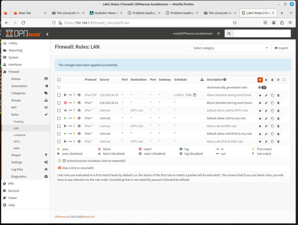
Let’s assume that we have decided to block Slashdot because we have decided that having workstations that can access Slashdot is counterproductive. But we also decide that we only want this rule to be applied during working hours – Monday through Friday, 9 AM to 5 PM. We also decide that accessing Slashdot will be allowed during lunch hour: noon to 1 PM. Essentially, we have three separate tasks to complete:

  • Create a schedule entry for regular work hours.
  • Create another schedule entry for lunch time.
  • Create a rule to block Slashdot during work hours.
  • Create another rule to allow Slashdot at lunch time.
  • Test the rule to make sure it takes effect.

This may be fairly ambitious, but by focusing on each individual task, it should be possible. First, we log into OPNsense’s web GUI, and start to add schedule entries:

  • On the left sidebar menu, click on Firewall, click on Settings, and click on Schedule.
  • Click on the plus (+) icon to add a schedule entry.
  • In the Name edit box, enter WORK_HOURS.
  • In the Description edit box enter “Normal work hours”.
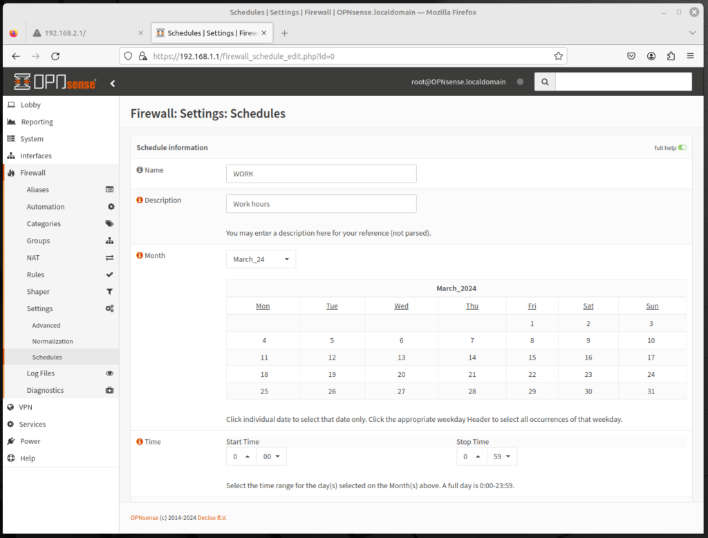
  • In the Month calendar, click on the headers or Mon, Tue, Wed, Thu, and Fri.
  • In the Time drop-down boxes, select 9:00 and 17:00.
  • In the Time Range Description edit box, enter “Standard Work Hours”.
  • Click on the Add Time button to add the time range.
  • Click on Save to Save the schedule entry.
  • Now you must add the lunch time schedule entry. Click on the plus (+) icon to add a schedule entry.
  • In the Name edit box, enter LUNCH_TIME.
  • In the Description edit box, enter “Normal lunch time”.
  • In the Month calendar, click on the headers or Mon, Tue, Wed, Thu, and Fri.
  • In the Time drop-down boxes, select 12:00 and 13:00.
  • In the Time Range Description edit box, enter “Standard Lunch Time”.
  • Click on the Add Time button to add the time range.
  • Click on Save to Save the schedule entry.

Now that we have schedule entries for work hours and lunch time, we can begin to add firewall rules:

  • On the left sidebar menu, click on Firewall, Rules, and LAN.
  • Click on the plus (+) icon to add a firewall rule.
  • In the Action drop-down box, select Reject.
  • In the Protocol drop-down box, select TCP.
  • In the Source drop-down box, select Single host or Network. In the edit box, enter 216.105.38.15. and select 32 in the CIDR drop-down box.
  • In the Schedule drop-down box, select WORK_HOURS.
  • In the Description edit box, enter a brief description (e.g. “Block Slashdot during work hours”).
  • Click on the Save button to save the rule, and Apply Changes to reload the rules.
  • We have created a rule to block Slashdot during work hours; now we just need to add a rule to allow Slashdot at lunch time. Click on the plus (+) icon to add a firewall rule.
  • In the Action drop-down box, select Pass (which should be the default).
  • In the Protocol drop-down box, select TCP.
  • In the Source drop-down box, select Single host or Network. In the edit box, enter 216.105.38.15. and select 32 in the CIDR drop-down box.
  • In the Schedule drop-down box, select LUNCH TIME.
  • In the Description edit box, enter a brief description (e.g. “Allow Slashdot during lunch time”).
  • Click on the Save button to save the rule, and Apply Changes to reload the rules.

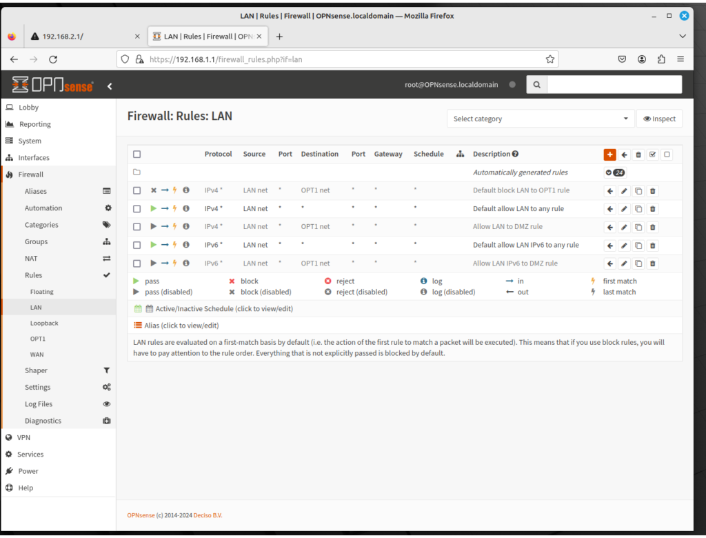
Now you have all the firewall rules, and you just need to order them properly. You need to put the new rules before the “Allow LAN to any” rules. In addition, you must put the “Allow Slashdot during lunch time” rule before the “Block Slashdot during work hours” rule. This is because firewall rules are evaluated from the top down, and once a rule matches traffic, the rest of the rules are not evaluated. Thus, the allow Slashdot rule must be evaluated before all other rules; the deny Slashdot rule should be evaluated next. You can put these rules first by checking all the other rules, then select the ← arrow (the icon for “Move selected rules to end”). Then select the all the old rules, the “Block Slashdot during work hours” rule and do the same. Now the rules should be in the right order.

Next, you should verify the rules to make sure they actually work. Unless you are testing this during work hours, you probably should edit the Block Slashdot firewall rule. Scroll down to the Schedule drop-down box, and select any. Then save the rule. Edit the Allow Slashdot rule, and disable the rule temporarily. Now, if you surf to slashdot.org, the site should be blocked now. Once you have confirmed that this is actually the case, edit the Allow Slashdot rule. Re-enable it, and scroll down to the Schedule drop-down box and select any. Now, Slashdot should be allowed. Once you have confirmed this, re-edit the rules to apply to the schedule entries, save both of them, and click on Apply Changes to reload the firewall rules.

Admittedly, this was a relatively simple rule set. Most web sites actually have multiple web servers (and therefore, multiple IP addresses) which are used to host content to the rest of the world; Slashdot is unique in that it only has a single IP address. We will examine how to come up with a rule set to block social media sites in a future article.

How to Schedule a Rule in OPNsense

Rules don’t have to take effect at all times. We can define time ranges during which the rules apply, and the process is even easier than creating rules. Each rule can have a different time range, or multiple time ranges, and once these ranges are defined, it can be applied to a rule.

To add a schedule entry, do the following:

  • Log into the OPNsense web GUI, and on the left sidebar menu, click on Firewall, click on Settings, and click on Schedule. Then click on the plus (+) icon to add a schedule entry.
  • In the Name edit box, enter a name for this schedule entry. (e.g. WORK_HOURS).
  • In the Description edit box, enter a brief (non-parsed) description.
  • In the Month drop-down box, select the month. There will be a monthly calendar for the selected month. Click on an individual date to select a date, or click on the day header at the top of the calendar to select a day of the week (e.g. Monday or Wednesday).
  • In the Time drop-down box, select the Start Time and the End Time for the schedule entry.
  • In the Time Range Description edit box, enter a (non-parsed) time range description.
  • Click on the Add Time button to add this time to the schedule entry, or Clear Selection to reset the page.
  • When you are done making changes, click on the Save button (or Cancel) to save the schedule entry.

This will save a schedule entry, which we can then apply to a firewall rule. To apply the schedule entry to a firewall rule, on the left sidebar menu, click on Firewall, click on Rules, and click on the interface to which the rule will apply. Then scroll down to Schedule, and from the drop-down box, select the schedule entry which was defined previously.

In the next article, we will show how to apply a schedule in a real-world scenario. But until then, this should help you get started in scheduling.

How to Add a Floating Firewall Rule

Floating firewall rules are rules that are different from other firewall rules in two significant ways:

  • They can be applied in any direction (both into the interface an out of the interface)
  • They can be applied to more than one interface

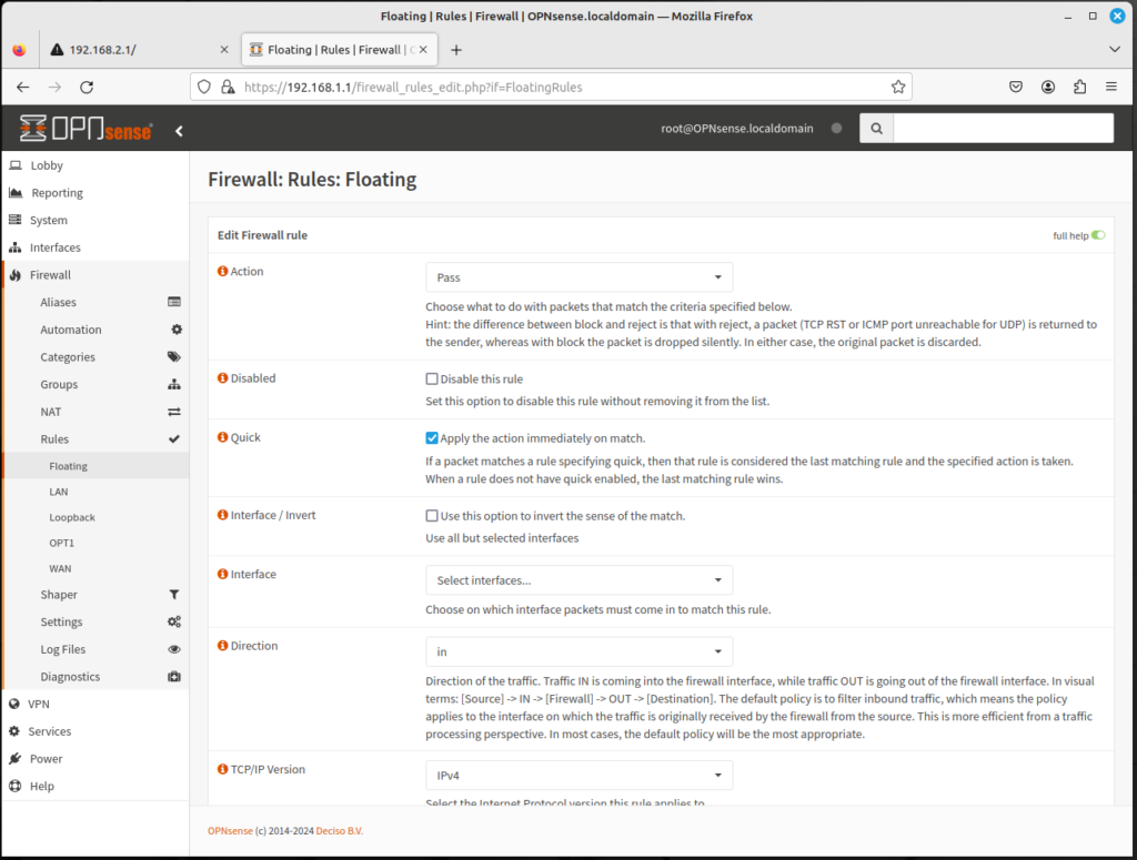
Floating rules can be created by navigating to the left sidebar menu, clicking on Firewall, clicking on Rules, and clicking on Floating; then you can add a rule by clicking on the plus (+) icon. The options are similar to those in a typical add firewall rule page, with the following exceptions:

  • The Quick checkbox, if checked, will cause OPNsense to apply the rule to packets matching the rule and OPNsense will not attempt to filter the packets against any other rules.
  • In the Interface listbox, more than one interface may be selected.

In general, floating rules are a special type of rule that can act on multiple interfaces, and on inbound traffic, outbound traffic, or in both directions. In OPNsense, however, interface rules can act on traffic from any or both directions.

Keep in mind that floating rules are parsed before other rules, so even if the Quick option isn’t enabled, a misconfigured floating rule could easily defeat the purpose of rules on individual interfaces.

To create a floating firewall rule, do the following:

  • Click on the plus (+) icon in Firewall RulesFloating.
  • In the Action drop-down box, select Pass to allow the packet, Block to block the packet, and Reject to reject the packet. The difference between Block and Reject is that reject will explicitly reject the packet, so the application or end user will know about the rejection, whereas Block will silently drop the packet.
  • In the TCP/IP Version drop-down box, select IPv4, IPv6, or IPv4+IPv6.
  • For Protocol, select the relevant protocol: TCP, UDP, TCP/UDP, or ICMP.
  • For Source/Invert, clicking on this option inverts the sense of the match. Leaving the option unchecked does nothing.
  • In the Source drop-down box, select This Firewall, any of the interfaces added to OPNsense (net or address), or any.
  • If you selected a protocol, in Source drop-down box, select any of the pre-defined ports (e.g. FTP, HTTP, etc.), or enter your own port number.
  • In the Source drop-down box, select This Firewall, any of the interfaces added to OPNsense (net or address), or any.
  • If you selected a protocol, in the Destination drop-down box, select any of the pre-defined ports (e.g. FTP, HTTP, etc.), or enter your own port number.
  • In the Log check box, select this option if you want packets handled by this rule to be logged.
  • In the Category edit box, enter a (non-parsed) category.
  • In the Description edit box, enter a brief (non-parsed) description.
  • In No XMLRPC Sync, selecting this option prevents the rule (on Master) to automatically syncing to other CARP members.
  • In the Schedule drop-down box, select a predefined schedule option to only enforce the rule at a specific time. Do nothing to enforce the rule at all times.
  • In the Gateway drop-down box, select a gateway for policy-based routing, or leave it as default to use the system routing table.
  • Click on Advanced Features to display a set of advanced features for floating rules, including priority, timeouts, and TCP flags.
  • When you are done configuring options, click on Save at the bottom of the page to save the rule, and click on Apply Changes to reload the firewall rules.

In general, it is better to add and configure rules on a per-interface basis than having floating rules, and if you misconfigure a floating rule, things can go very wrong on your network. But if you know what you’re doing, floating rules can represent a powerful tool.

Best Practices for Firewall Rules

Now that we have described how to add a firewall rule, it may be a good time to articulate a set of best practices for firewall rules. As with the rules for pfSense, some of these rules might be obvious, but some may not be so obvious.

  • The principle of least privilege should apply to our rules. In many cases, our firewall rules have become too permissive. You should avoid creating rules with any in the destination field (these are known as pass-through rules). At the very least, you should limit the range of ports on which these rules apply. OPNsense blocks all traffic by default, and we want to take advantage of that. This leads us to a corollary:
  • Block by default. Block all traffic by default and explicitly enable only specific traffic to known services, which will provide good control over the traffic and reduce the possibility of a breach because of service misconfiguration.
  • Firewall rules should be periodically checked, and obsolete rules should be deleted. For example, at one time we had a printer on the LAN network that workstations on other network would need permission to access; therefore rules had to be created granting access to this resource. If the printer were subsequently decommissioned or moved to another network, then the rule granting permission to the printer’s IP address would have to be deleted (or modified). In a corporate environment, you may have to be proactive, since different departments may not communicate this information. Nevertheless, it is an important practice, as deleting firewall rules eliminates a potential attack vector.
  • Firewall rules should be properly documented. Even if you remember why a rule was added a a rule change was made, others may not remember, especially if the rule change was made in response to an emergency. Documenting rule changes makes firewall management easier and can be helpful in a troubleshooting scenario.
  • Firewall rules should be backed up. This can be done in OPNsense by navigating to the left sidebar menu, clicking on System,, clicking on Configuration, and clicking on Backups. [A separate article on configuring backups will be posted soon.] In a corporate environment, such backups should be maintained offsite. Such backups may prove to be of value if you ever have to recover from a firewall crash or some other catastrophe.
  • Create your rules in a manner consistent with the company’s security policy. When you are done creating them, you should review them to make sure they are consistent with such policy.
  • Eliminate redundant and unnecessary rules. Try to keep your ruleset as simple as possible.
  • Patch the firewall. Patch it with the latest updates on a regular basis.
  • Maximize CPU cycles. To this end, you should limit the number of applications running on the firewall. Any applications that can be run on a dedicated machine (e.g. a proxy server) should be moved to another system either behind or in front of the firewall.
  • Test your firewall. It is important that you perform regular security tests on your firewall. New exploits are being found and the firewall should be tested on a regular basis. This should include testing every interface on both sides of the firewall.
  • Comply with PCI DSS, if necessary. You will want to review your policies to make sure you are in compliance with this standard. For example, PCI requirement 1.1.6 requires a complete firewall review every six months. PCI DSS is constantly being updated – as of this writing, Version 4.0 was scheduled for release in March 2022– so you need to review the latest version of the standard to see if there are any new requirements that affect firewall implementation.
  • Enable logging. You should only do this if you are going to read the logs. Otherwise, maintaining logs is a waste of both disk space and CPU usage.
  • Implement posture assessment. If you have remote users, you should require that they run a personal firewall and/or intrusion detection system on their computer. You can’t trust every computer, and some computers may be running questionable applications. If possible, you should implement a system that performs a health check on remote computers. Is the computer running anti-virus? If so, which version? What kind of personal firewall are they running? It would behoove you if you have a posture assessment that applies to all platforms (e.g. Windows, Linux, Mac OS, Android, iOS).
  • Enable Syslog. You may also consider running a remote syslog server for logging, to make it more difficult for potential hackers to modify the log files and thus cover their tracks.

You may possibly add to these general principles, but it’s a good set of guidelines for creating firewall rules.

Configuring Virtual IPs in OPNsense

Virtual IPs refer to a situation where a single IP address does not correspond to a single physical address. The situation presented involves many scenarios; these scenarios include the following:

  • NAT, including one-to-many NAT
  • CARP, and scenarios where fault tolerance is required
  • Mobile IP scenarios, including situations where a mobile user has the same IP address even as their actual IP address changes

To add a Virtual IP, do the following:

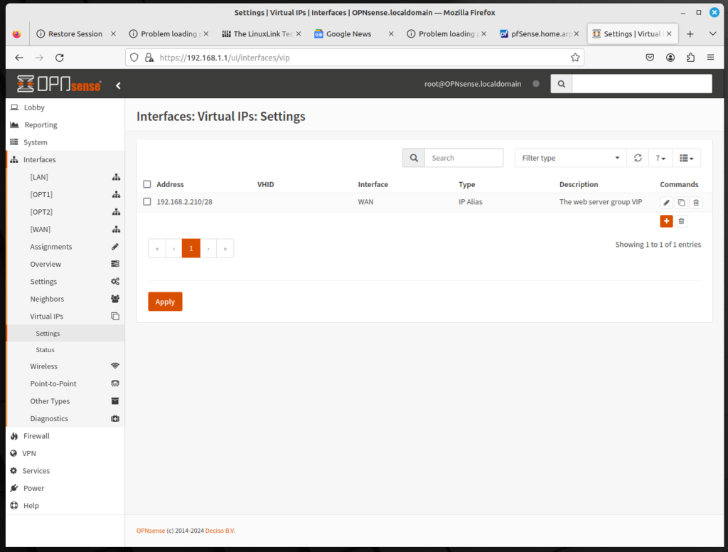
  • Log into the OPNsense web GUI, and on the left sidebar menu, click on Interfaces, click on Virtual IPs, click on Settings, and click on the plus (+) icon to add a rule.
  • You can now add a Virtual IP. OPNsense offfers four options for a Virtual IP:
    • IP Alias: IP aliases work like any other IP address on an interface such as the actual interface IP address. They will respond to layer 2 (thus, they can be used by Address Resolution Protocol, or ARP). They can also be used as binding addresses by services on the firewall. OPNsense will respond to a ping on an IP alias, and services that bind to all interfaces will also respond on IP Alias VIPs unless the VIP is used to forward those ports to another device.
    • CARP: This refers to Common Address Redundancy Protocol. It’s primarily used with High Availability redundant deployments using CARP. CARP VIPs have their own unique MAC address derived from their VHID.
    • Proxy ARP: Proxy ARP provides ARP replies for the specified IP address or a CIDR range of IP addresses. This allows OPNsense to accept traffic targeted at addresses inside a shared subnet.
    • Other: Other type virtual IPs define additional IP addresses for use when ARP replies for the IP address are not required.
  • To create a Virtual IP first select one of the four options. Then select a physical interface in the Interface drop-down box.
  • In the Address edit box, you can provide the IP address and the subnet to use.
  • In the Deny service binding checkbox, check this option if you don’t want services to bind to the virtual IP address.
  • The VHID group box can be left blank, unless you are configuring a CARP virtual IP. Otherwise, you must enter a number from 1 to 255.
  • In the Description edit box, enter a brief description.
  • Click on the Save button at the bottom of the page to save this virtual IP address, and click on Apply at the bottom of the page to reload the firewall rules.

That handles the settings for IP Alias. With other options, there are more settings:

  • For CARP, in the Password edit box, enter the VHID password.
  • For CARP, in the advbase edit box, enter the base of the advertising interval, in seconds. Acceptable values are from 1 to 255.
  • For Proxy ARP, in the Disable Expansion edit box, check this box to disable the expansion of this entry IP onto NAT lists.

If you have followed this configuration, you will have successfully added a virtual IP.

Configuring 1:1 NAT in OPNsense

1:1 NAT allows you to map one public IP to one private IP; all traffic from that private IP to the Internet will then be mapped to the public IP specified in the 1:1 NAT mapping. This will override the Outbound NAT settings. Conversely, all traffic initiated on the Internet which is destined for the specified public IP address will then be translated to the private IP. Then it will be evaluated according to the WAN firewall ruleset, and if the traffic is permitted by the WAN rules, it will be passed to the internal node specified in the mapping.

In this scenario, the server should be accessible via the public WAN network. Thus, we will have an additional IPv4 address in each WAN network. The addresses must match the IP network and be known to the clients (e.g. via DNS).

The implementation in OPNsense is somewhat complicated because for practical purposes, the firewall requires:

  • Virtual IPs
  • 1:1 NAT
  • Firewall rules

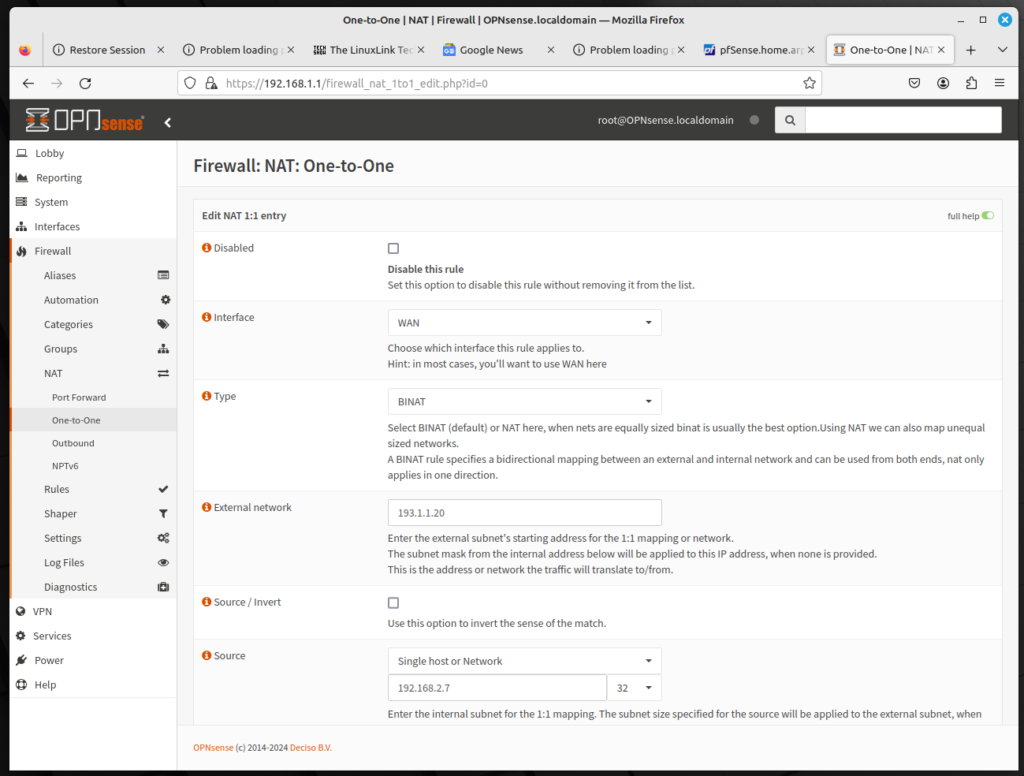
Virtual IPs and firewall rules have articles devoted to each settings. Assume that 192.168.2.7 is the virtual IP for the web server. To configure 1:1 NAT, do the following:

  • Log into the OPNsense web GUI; on the left sidebar menu, click on Firewall, click on NAT, and click on One-to-One
  • Leave Interface as WAN and for Type, leave it as BINAT. With BINAT, networks are equally sized; the NAT option allows us to map unequally sized networks
  • For External network, enter the external network’s starting address.
  • For Source, select Single host or Network, and type 192.168.2.7 in the edit box.
  • For Description, enter a brief description (e.g. “1:1 web server”).
  • For NAT reflection, leave the selection as Use system default. NAT reflection is a method that allows communication of internal PCs (behind the firerwall) to access a DMZ server using the public IP address instead of the private IP address.
  • At the bottom of the page, click on Save to save the entry, then click on Apply Changes to reload the firewall rules.

You have now successfully configured 1:1 NAT for the externally-facing server.

NAT Configuration in OPNsense

A router or firewall can modify the IP address of packets passing through them; this is done on purpose to implement the network design. This is commonly known as Network Address Translation (NAT).

In a nutshell, IPv4 uses 32-bit addresses, capable of uniquely addressing about 4.4 billion devices. By 1992, it become evident that that would not be enough. In 1994, RFC 1631 was issued, which described NAT as a short-term solution to the two most compelling problems facing IP addressing at the time: IP address depletion and scaling in routing. By 2004, NAT became widespread.

In the meantime, IPv6 has become widespread and has more than enough addresses and therefore does not rely on NAT. But in particular scenaros (e.g. failover with several ISPs), NAT has also crept into IPv6 designs.

Most ISPs use DHCP to dole out public IP addresses; thus every DSL router uses NAT so that all its clients can access the Internet via a single public IPv4 address. The hotspot function of a smartphone uses the same technology. Finally, a large corporate firewall uses a pool of IP addresses for address translation to enable Internet access for all clients.

How to Configure a NAT Rule

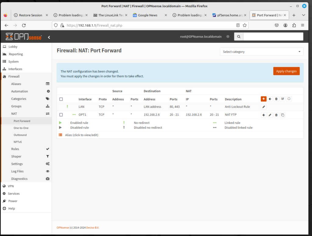
Configuring a rule for Network Address Translation is relatively easy. Let’s assume that we need to have a port open for our FTP server, whose IP address is 192.168.2.6. You will have to configure ports 20 (for data) and 21 (for commands) for port forwarding. To configure a NAT entry, do the following:

  • Log into the OPNsense web GUI; on the left sidebar menu, click on Firewall, click on NAT, and click on Port Forward.
  • In the Port Forward table, click on the plus (+) icon to add a rule.
  • For Interface, select OPT1 for the DMZ network.
  • Keep TCP/IP Version as IPv4 and Protocol as TCP.
  • For Destination, type 192.168.2.6 in the edit box.
  • For Destination port range, in the drop down box, select (other). Then in the edit boxes, type 20 and 21.
  • For Redirect target IP, type 192.168.2.6 in the edit box.
  • For Redirect target port, select (other) in the drop down box and type 20 in the edit box.
  • For Log, select the check box.
  • In Description, type a brief description in the edit box (e.g. “FTP NAT”).
  • In Filter rule association, keep “Add associated filter rule”.
  • At the bottom of the page, click on the Save button to save the entry, then click on Apply Changes at the top of the page to reload firewall rules.
  • On the left sidebar menu, click on Rules, then click on OPT1. You should see the firewall rule for FTP. If you want to alter the order of the rules, you can do that here.

Once you have done this, your Internet-facing FTP server at 192.168.2.6 should be publicly available. There are three other forms of NAT to consider: One-to-one, Outbound, and NPTv6. We will configure these in future articles.

Creating Firewall Rules in OPNsense

OPNsense is essentially software that works as both a router and a firewall. It is a router because it can route traffic from one network to another; it is a firewall because it can block traffic from one network to another. A firewall is implemented with packet filters, gateways, demilitarized zones, encryption and logging. Network Address Translation (NAT) may be part of a firewall, but it will be discussed in a separate article.

A firewall may not just be a packet filter; it may incorporate higher levels of security: systems for detecting and preventing intrusions for packets that should not be there due to security rules. A firewall may incorporate a honeypot, or a honeynet, which rebuilds a regular network with fake hosts which allows the security team to study attack patterns.

For purposes of this article, we will consider firewall rules. OPNsense is a stateful firewall, which means that it is connection-oriented. The reply packets of a connection do not require a separate rule – they are automatically allowed.

The first match rule makes the order of the rules important. Rules are evaluated from the top down; if the packet matches the rule, this rule is evaluated and the rest are ignored. A blocking rule at the beginning of the ruleset makes the rest of the rules ineffective.

The rules should be sorted by this plan:

  • Rules that match packets with bogus addresses are blocked (anti-bogon rule).
  • The ruleset – rules in the list – are matched next:
    • The upper part of the list should contain rules with detailed information about the source IP, destination IP, and ports (and possibly other details, such as protocol and TCP flags).
    • The lower part of the list should host the general rules. These rules filter by source and or destination networks, with or without ports.
    • Next, put the rule which silently drops everything that should not appear in the log file.
    • Finally, add a rule that denies everything and logs all the denied packets. By default, OPNsense drops unmatched packets, but this rule is easy to switch on and off and is a good rule for troubleshooting.

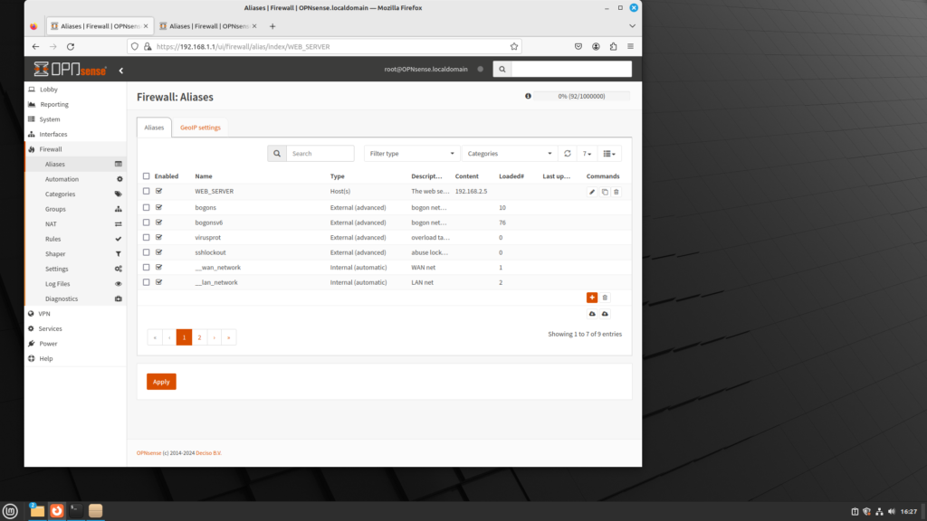
Let’s assume you need a rule to allow traffic to pass on port 80 for the web server, which has an IP address of 192.168.2.5. Do the following:

  • Log into OPNsense; on the left sidebar menu, click on Firewall, and click on Aliases.
  • Click on the plus (+) icon to add an alias.
  • For Name, type in WEB_SERVER.
  • For content, type in 192.168.2.5.
  • Click on the Save button to save this alias.
  • Log into OPNsense; on the left sidebar menu, click on Firewall, click on Rules, and click on OPT1.
  • Click on the plus (+) icon to add a rule.
  • On Protocol drop down menu, select TCP.
  • On the Destination drop down menu, select Single host or Network, then enter WEB_SERVER in the edit box.
  • On the Destination port range, select other, then enter 80 in the edit box.
  • In the Description field, enter “Allow HTTP to web server”.
  • Click on the Save button at the bottom of the page to save the rule, then click on Apply Changes at the top of the screen to reload the firewall rules.

Configuring DHCP in OPNsense

If you only have a few devices on your network, you could easily configure them with static IP addresses and not use a DHCP server at all. In such cases, Internet connectivity will be established more quickly, since computers on the network won’t have to go through the DHCP discovery-offer-request-acknowledge process. As the size of your network grows, however, a DHCP server becomes essential, as keeping track of statically assigned IP addresses will become far too cumbersome.

Moreover, if two nodes have the same IP address, this constitutes an IP address conflict, which is not good, for a variety of reasons:

  • It can cause network connectivity problems;
  • It can cause network outages, as the network becomes unable to route data to the correct device;
  • If two devices have the same IP address, incoming traffic intended for one device may be incorrectly routed to the other device, causing data to be lost or transmitted to the wrong device.

In most cases, if two nodes have the same IP address, the router will recognize one device and ignore the other node, so the only issue is figuring out why one node can’t communicate on the network. Still, it’s beneficial to enable the DHCP server.

Fortunately, configuring OPNsense to act as a DHCP server is relatively easy, and can be done from either the console or the web GUI.

Configuring DHCP from the console is simple, although it doesn’t have as many options. To configure DHCP at the console, do the following:

  • At the console, select “Set Interface IP address”
  • Select the interface on which you want to enable DHCP (e.g. 1=LAN, 2=OPT1, etc.). For the next steps, x=the interface selected.
  • You will have to configure the IP address for the interface. For “Configure IPv4 address x interface via DHCP? [y/N]”, type ‘N’ and press Enter.
  • Type in the new x address and the new subnet bit count (probably 24).
  • For the interface upstream gateway address, press Enter.
  • For “Configure IPv6 x interface via x tracking? [Y/n]”, type ‘N’ and press Enter.
  • For “Configure IPv6 x interface via DHCP6? [Y/n]”, type ‘N’ and press Enter.
  • Type in the new IPv6 x address and the new subnet bit count (probably 64).
  • For the IPv6 LAN upstream gateway address, press Enter.
  • The console will query “Do you want to enable the DHCP server on x? [y/N]”. Type y and press Enter.
  • Enter the start IP address for the scope and press Enter.
  • Enter the end IP address for the scope and press Enter.
  • The console will query “Do you want to enable the DHCP6 server on LAN? [y/N]”. You may or may not want to enable the DHCP6 server on the LAN. If so, you will have to enter the start IPv6 address and the end IPv6 address.

If you follow all these steps, you will have successfully configured DHCP at the console in OPNsense. But there are some drawbacks. First, you entered some parameters irrelevant to enabling DHCP. Second, you only configured a fraction of the options available that would be available in the web GUI. If you want to configure many of the options available, you will have to configure DHCP in the web GUI.

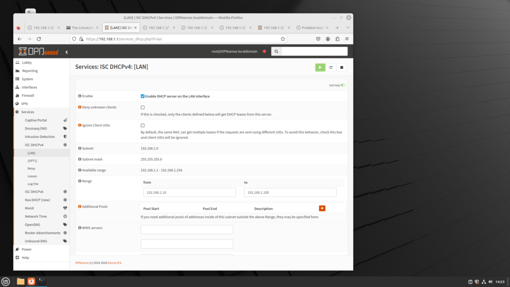
To configure DHCP in the web gui, access OPNsense’s IP address and log in. Then do the following:

  • In the left sidebar menu, click on Services.
  • In the left sidebar menu, click on ISC DHCPv4.
  • Click on the interface on which you want to enable DHCP; e.g. LAN
  • The page will have a series of DHCP settings; e.g.:
    • Enable: This will enable the DHCP server on this interface.
    • Deny unknown clients: If this option is checked, then only the clients defined in MAC Address Control will get DHCP leases from the server.
    • Range: The scope of IP addresses used for DHCP leases. Note that the range previously specified at the console (192.168.2.10 to 192.168.2.100) is in the edit boxes.
    • Additional Pools: You can specify additional pools by clicking on the plus (+) button.
    • WINS servers: This allows you to specify the IP addresses of systems running Windows Internet Name Service (WINS), a legacy computer name resolution system that maps NetBIOS names to IP addresses.
    • DNS servers: You can specify DNS servers, or leave these edit boxes blank to use the system default DNS servers.
    • Gateway: You can use this to specify a gateway IP that is not the IP of this interface.
    • Domain name: This is for an alternate domain name.
    • Default lease time (seconds): This is used to specify a lease time if clients do not ask for a specific lease time; the default time is 7200 seconds.
    • Maximum lease time (seconds): This is the maximum lease time for clients that ask for a specified maximum lease time; the default is 86400 seconds.
    • Response delay (seconds): This is the minimum number of seconds since a client began trying to acquire a lease before the DHCP server responds; the default is 0 seconds.
    • Interface MTU: This is the minimum transmission unit to use; the default is 68
    • Failover peer IP: This is the IP address of an alternate router using Common Address Resolution Protocol (CARP). The default is no IP address.
    • Failover split: Use this to specify the load balancing split for a load balancing split; the default of 128 has the primary handling a 50-50 split, while 256 will exclusively use the primary.
    • Static ARP: If this option is enabled, only the machines listed in the MAC Address Control will be able to communicate via Address Resolution Protocol (ARP).
    • MAC Address Control: The first edit box lists MAC addresses to allow access to; the second edit box lists MAC addresses to deny access to
    • DHCP Static Mappings: Here, you can use this to specify an IP address for nodes that require a static IP address; e.g. a web server or an FTP server. Click on the plus (+) icon to add to the DHCP Static Mappings. There you will find the following settings:
      • MAC Address: Here, you can specify the MAC address for the Network Interface Card (NIC) on the node. You can click on “Copy my MAC address” to copy the MAC address on the node from which you are accessing the web GUI.
      • Client identifier: the identifier of this client.
      • IP address: The IP address for the node. The IP address must be part of the subnet for this interface.
      • Hostname: Name of the host, without the domain part.
      • Description: A brief description of this node.
      • ARP Table Static Entry: Enabling this option allows you to create a static ARP table entry for this MAC and IP address pair.
      • WINS servers/DNS servers/Gateway/Domain name/Domain search list/Default lease time/Maximum lease time(seconds): See above.
      • Dynamic DNS domain: You can use this to enter the dynamic DNS domain, which will be used to register this client.
      • NTP servers: Use this to add an NTP (Network Time Protocol) server
      • TFTP server: Use this to add a TFTP (Trivial File Transfer Protocol) server and bootfile
  • When you are done making changes, click on the Save button at the bottom of the page.

If you have followed all the steps, you have configured IPv6 successfully. But there is still one more question that deserves attention.

Should I Enable DHCPv6?

If your network relies on IPv4, and has more than a dozen nodes, you instinctively want to enable DHCP, which exists because of concern over IPv4 address scarcity. Essentially, DHCP is an efficient manner of allocating scarce resources (private IPv4 addresses). Is this the case for DHCPv6? Not really. The total number of IPv6 addresses is 3.4 * 10^38, so even a randomly chosen IPv6 address will likely not generate an address conflict.

However, there are several advantages to using DHCPv6:

  • If VLANs are enabled, then enabling DHCPv6 allows the switch to obtain a global unicast address.
  • Enabling DHCPv6 allows the switch to obtain additional information such as an NTP server address or a DNS server address that can be used by the switch.

Keep in mind that a DHCPv6 server does not assign link-local addresses and enabling DHCPv6 on a VLAN does not affect a pre-existing link-local address.

To configure DHCPv6 on an interface, just repeat the same steps as outlined for IPv6, but instead of clicking on Services, ISC DHCPv4 and the interface, click on Services, ISC DHCPv6 and the interface. Much of the parameters for IPv4 are the same in IPv6, with some exceptions:

  • Prefix Delegation Range: If your router has a number of subrouters, then you can assign a network to the subrouters. Note that the start and end of the range mus end on boundaries of the prefix delegation size. Ensure that any prefix delegation range does not overlap the interface prefix range.
  • Subnet mask: The subnet mask cannot be changed.

It’s up to you to decide to enable DHCPv6, but you can do this easily in OPNsense.