Configuring the DMZ in OPNsense in 3 Easy Steps

Now that we have set up the WAN and LAN networks, we should consider configuring the DMZ.

The DMZ (demilitarized zone), or screened subnet, is physical or logical subnetwork that exposes an organization’s external-facing servers to the Internet. The purpose of the DMZ is to add an extra layer of security to a LAN. With a DMZ, an external node in the DMZ can only access hosts in the DMZ, while the rest of the network is hidden behind a firewall.

To configure the DMZ, three steps are necessary:

  • Enabling the DMZ
  • Adding firewall rules to the DMZ
  • Testing the DMZ to confirm security

In this article, we will cover all three steps.

Enabling the DMZ

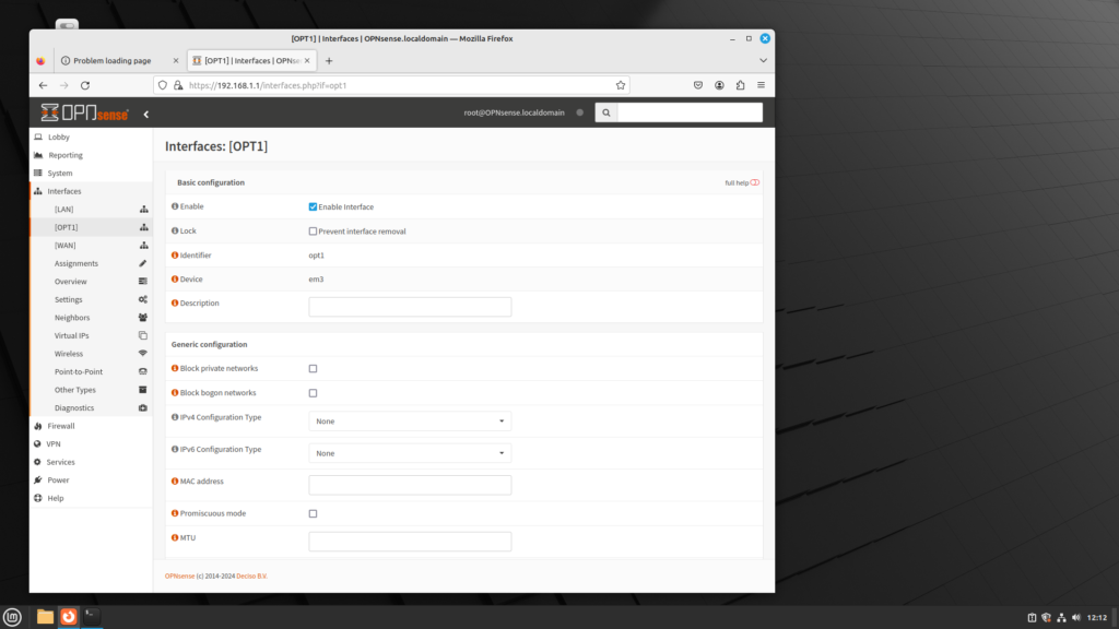
In order to enable the DMZ (which is referred to as OPT1), do the following:

  • Log into the web GUI.
  • On the left menu sidebar, click on Interfaces.
  • On the left menu sidebar, click on OPT1.
  • The OPT1 web page offers a number of different parameters:
    • Description: This is where you can enter a brief description
    • Block private networks/Block bogon networks: Just as in the configuration page for WANs, you can prevent private addresses from being sent and prevent reserved and unassigned IP addresses from being sent. For most cases, these options should be left unchecked.
    • IPv4/IPv6 Configuration Type: Unless you have an upstream DHCP server, you should select Static IPv4/Static IPv6.
    • MAC Address: You can enter a different MAC address, which enables MAC spoofing.
    • MTU/MSS/Duplex and Speed: You can alter the maximum transmission unit (default is 1500), the maximum segment size (default is 536 for IPv4, 1220 for IPv6). You can also change the duplex and speed, from 10 Base T to 1000 Base T, and select between half and full duplex.
    • Static IPv4/IPv6 Configuration: Since you selected static configuration, you must enter an IP address here. If you used 192.168.1.0/24 for the LAN, you likely should enter 192.168.2.1 here for IPv4, and fd00:2::1 for IPv6.
    • IPv4/IPv6 Upstream Gateway: This is for a separate upstream link; it should be left as Auto-detect.
    • Uses IPv4 connectivity: If IPv6 is supplied over a PPoE connection, you need to check this option.
  • When you are done making changes, click on the Save button at the bottom of the page, then click Apply Changes at the top of the page.

Adding Firewall Rules to the DMZ

As of now, we have enabled and configured the DMZ interface. But the reason we added a DMZ was so front-facing servers could be exposed to the Internet, with all other nodes behind the firewall. But for that to happen, we must add firewall rules.

  • On the left menu sidebar, click on Firewall.
  • On the left menu sidebar, click on Rules.
  • On the left menu sidebar, click on LAN.
    • There are two pre-defined rules to ensure that the LAN can interact with the Internet: the default “Allow LAN to any” rule and the default “Allow LAN IPv6 to any” rule. We need to clone these two rules for the DMZ (OPT1).
    • For the “Allow LAN to any rule”, click on the clone (depicted as two pieces of paper) icon to copy it. This rule should remain the same, with the following exceptions:
      • The Interface should be changed to OPT1.
      • The Source should be changed to OPT1 net.
      • The Description should be changed to “Default allow DMZ to any rule”.
      • Click on the Save button on the bottom of the page to save the rule.
    • For the “Allow LAN IPv6 to any rule”, again click on the clone icon to copy it. This rule should remain the same, with the following exceptions:
      • The Interface should be changed to OPT1.
      • The Source should be changed to OPT1 net.
      • The Description should be changed to “Default allow DMZ to any rule”.
      • Click on the Save button at the bottom of the page to save the rule, then click on the Apply Changes button at the top of the page to reload the firewall rules.
    • Now the DMZ can interact with the Internet, but the LAN still has to interact with the DMZ. We can make rules by cloning the default rules and making changes to them.
    • For the “Allow LAN to any rule”, click on the clone icon to copy it. This rule should remain the same, with the following exceptions:
      • Destination should be changed to OPT1 net.
      • Description should be changed to “Allow LAN to DMZ rule”.
      • Click on the Save button at the bottom of the page to save the rule.
    • For the Allow LAN IPv6 to any rule”, again click on the clone icon to copy it. This rule should remain the same, with the following exceptions:
      • Destination should be changed to OPT1 net.
      • Description should be changed to “Allow LAN IPv6 to DMZ rule”
      • .Click on the Save button at the bottom of the page to save the rule, then click on the Apply Changes button at the top of the page to reload the firewall rules.

Test the Network to Confirm Security

Now you have added the DMZ interface and the firewall rules so that the LAN can interact with the DMZ, but the DMZ cannot interact with the LAN. But we don’t know whether it works or not until we add a node to both the LAN and the DMZ to test the network. To confirm that the network works, do the following:

  • From the DMZ node, ping a server on the Internet. The ping should be successful.
  • From the LAN node, ping the DMZ node. The ping should be successful.
  • From the DMZ node, ping the LAN node. The ping should not be successful.

If all three criteria are met, then it looks like the network works, and you can begin deploying your Internet-facing servers. You should be aware that you will have to configure NAT and a firewall rule for each server, and you will likely have to test connectivity to the server as well. But by following these steps, you will have successfully deployed a DMZ/screened subnet in OPNsense.
Configuring VLANs in OPNsense

Now that we have configured the WAN, LAN and DMZ networks, we can configure Virtual LANs (VLANs). The word “virtual” is key: unlike traditional networking, in which networks are separated by routers, and each network has at least one switch, VLANs allow us to have several networks on one switch. This can be advantageous, for a variety of reasons:

  • Each VLAN forms its own broadcast domain, limiting broadcast traffic and broadcast storms
  • VLANs can be configured so that even if we move to another physical location, we connect to the same VLAN, giving us considerable flexibility and eliminating administrative overhead
  • Each VLAN is segregated from each other, improving security.

Before you start configuring VLANs, you should have a network plan. For example, rather than create a network where several departments all have access to the network, you might think about dividing up the network by departments; e.g. we might have the following plan:

  • Sales
  • Marketing
  • Engineers
  • Developers
  • Technicians

This is only one way of dividing up our network. We might divide up our network in a different way:

  • C-level executives
  • Upper management
  • Middle management
  • Supervisors
  • Technicians

Configuring VLANs is so fundamental that we can configure VLANs in two different ways:

  • Configuration at the command line (console), and
  • Configuration within the web GUI

We will cover both configurations here.

Configuration at the Console

Configuration can be done at the console. In order to allow VLAN configuration, at least one interface must not have been allocated. Technically, you can use an interface that has already been allocated; for example, you could use the LAN or OPT1 network interface for VLANs. But it would not work well, and very likely, you will have to reconfigure the setup later.

In order to do VLAN configuration at the console, log into the console. There will be a menu for configuration. Select 1, which is Assign Interfaces.

  • Next, the console queries if you want to install LAGGs (Link Aggregation). Type ‘N’ and press Enter.
  • The console will query if you want to configure LANs. Type ‘Y’ and press Enter.
  • The console will list VLAN-capable interfaces, and their MAC addresses. Type the parent interface and press Enter.
  • The console will query you for the VLAN tag. Enter a number from 1 to 4094.
  • The console will again list VLAN-capable interfaces and their MAC addresses. Either type the parent interface, or nothing if finished.
    • Note that VLAN 0 and VLAN 4095 are omitted. That is because VLAN 0 will cause the VLAN tag to be ignored, while VLAN 4095 is reserved for internal use. All other tags are valid.
    • The console will ask you to designate a WAN and LAN interface (and possibly optional interfaces; it depends on how many network interfaces you have). Enter these interfaces.

Configuration in the GUI

Assuming you have logged into the web interface, do the following:

  • On the left menu panel, click on Interfaces
  • On the left menu panel, click on Other Types
  • On the left menu panel, click on VLAN
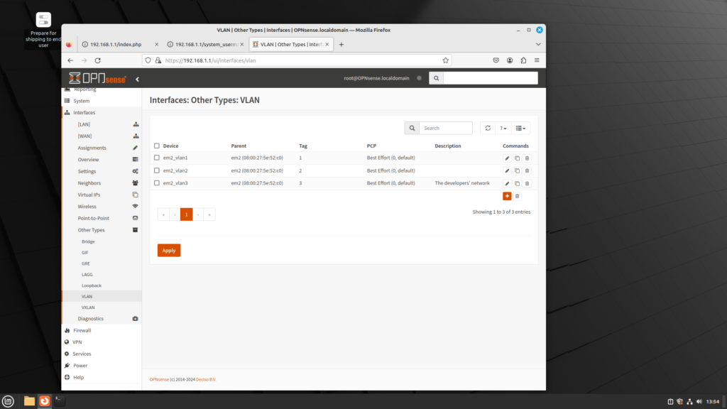
  • Here you will find a listing of the currently confifgured VLANs. You can add a VLAN by clicking on the plus (+) logo. Clicking on this logo will invoke the VLAN dialog box, where you can configure:
    • Device: the device name (e.g. em2_vlan1, em2_vlan2, etc.)
    • Parent: the parent device
    • VLAN tag: Any number from 1 to 4094.
    • VLAN priority: This allows you to utilize the 802.1Q priority code point (PCP) field. This is a 3-bit field which makes reference to the IEEE 802.1p class of service. 802.1p defines how traffic should be treated based on the value of this field, which corresponds to the values in this table:
PCP valuePriority levelDescription
01Traffic gets best effort treatment.
10Traffic is assigned the lowest priority. It is handled in the background.
22Traffic gets excellent effort treatment, which is one step below best effort.
33Suitable priority level for critical applications.
44Suitable for video requiring < 100 milliseconds of latency and jitter.
55Suitable for voice requiring < 10 milliseconds of latency and jitter.
66Suitable for internetwork control.
77Traffic gets highest priority.
  • Description: A brief description of this VLAN.
  • Clicking on the “Advance mode” button enables another option: edit VLAN. This option provides a drop-down box with the following options:
    • 802.1Q: This is the standard that makes VLANs possible.
    • 802.1ad: Old-school 802.1Q only allows 4095 VLANs. With the growth of networks, this has become more problematic. 802.1ad allows an additional tag nested inside a single-tagged 802.1Q packets, also known as “Q in Q”.
    • Auto: Allows OPNsense to detect whether the switch supports Q in Q tagging; if it detects this, then 802.ad will be enabled; otherwise, 802.1Q is enabled.
  • Click on the “Apply” button to apply settings.
  • You can delete VLANs by clicking on the trash logo.

From my cursory look at VLAN support in OPNsense, it seems that OPNsense does not have as many options as pfSense, although it does support VLAN priority and 802.1ad, as well as link aggregation (LAGG).

There are two steps to VLAN configuration that we didn’t cover here:

  • VLAN configuration at the switch
  • Verifying VLAN configuration

I will cover both topics in a future article, so stay tuned for that.

Installing OPNsense in 5 Easy Steps

How to Install OPNsense in 5 Easy Steps

OPNsense is a FreeBSD-based firewall and routing software. It is a fork of pfSense, which in turn is a fork of the m0n0wall project. OPNsense launched in January 2015; it was named OPNsense when m0n0wall closed down in February 2015.

OPNsense can run on x86_64 processors, and as it’s based on Free BSD, a Unix derivative, it can run on more lightweight hardware than Windows. And it is free; you can download it from the OPNsense website with no licensing involved. Although configuring OPNsense requires more time and resources than commercial software, you can install OPNsense in five easy steps and start tinkering with the settings, and see if OPNsense meets your requirements. If it does, you will likely save money.

  1. Find out if your hardware meets the minimum hardware requirements. If your hardware does not meet the minimum specifications, it seems logical that you cannot install OPNsense. Fortunately, the hardware requirements are fairly simple, and are listed on the OPNsense website as minimum specification, reasonable specification, and recommended specification. These requirements are summarized in the following table:

MinimumReasonableRecommended
Processor1 GHz dual core CPU1 GHz dual core CPU1.5 GHz multi core CPU
RAM2 GB4 GB8 GB
Install methodSerial console or video (VGA)Serial console or video (VGA)Serial console or video (VGA)
Install targetSD or CF card with a minimum of 4 GB; use nano images for installation40 GB SSD; a minimum of 2 GB is needed for the installer to run120 GB SSD

If you are purchasing hardware or installing it on a virtual machine, it behooves you to use the reasonable or recommended specifications to inform your decisions. But if you have existing hardware, the minimum specification should clue you in as far as the hardware is concerned.

  1. Download OPNsense. You can download OPNsense at the official OPNsense website [https://opnsense.org/download/]. Although there is only one option for the CPU (amd64), there are several options for the image type:
    1. DVD (ISO image installer with live system capabilities running in VGA mode; UEFI boot is supported, as well as legacy boot)
    2. VGA (USB installer image with live system capabilities running in VGA mode; again, UEFI and legacy boot are supported)
    3. Serial (USB installer image with live system capabilities running in serial mode; supports UEFI and legacy boot)
    4. Nano (a preinstalled serial image for USB sticks, SD or CF card as MBR boot; these images are 3G in size and automatically adapt to the installed media after the first boot

After you have downloaded the image, it is probably a good idea to run a checksum on the downloaded image. The checksum is listed on the download page on the official OPNsense website. Verifying the checksum guarantees:

  • that the downloaded file downloaded successfully;
  • that the downloaded file was not corrupted in any way.

You can download a checksum checker from these sites:

  1. Transfer the image file to the appropriate media for installation. As of now, you have the OPNsense image file. You need to transfer the image to the installation media. If you are installing OPNsense to a virtual machine, then you can skip this step; you just need to specify the image file when you are configuring settings for the virtual machine. If the system to which you are installing OPNsense has an optical drive, you may burn the image to a DVD. But if the system does not have an optical drive and has a USB interface, you might write the image to a USB thumb drive. Writing an image to a USB drive has several advantages:
  • It’s easy to do with the right software;
  • It’s relatively cheap, with a 16 GB Sandisk thumb drive costing only $5;
  • It’s very compact, as compared to a DVD;
  • Depending on the speed of your USB interface, it may be faster than a DVD;
  • Unlike a DVD, you can rewrite the image.

Keep in mind that your device may not support USB (although at this point, with USB having been produced since May 1996, it’s harder to see this as a rationale), and continued writes will reduce the life span of the device. But in reality, you’re more likely to physically damage a USB thumb drive than reach the end of life for a thumb drive by constant re-writes.

In any case, here are some programs you can use to write images to a thumb drive:

If you want to burn an image to a DVD, there’s the always excellent CD Burner XP available

  1. Using the installation media, boot the target system and begin installation. If you are using a DVD, this may be as easy as inserting the DVD into the optical drive and booting the system, as many systems check the optical drive first. If this is not the case, or if you are using a USB thumb drive, you may have to run the BIOS/UEFI settings, or run a one-time boot menu.

Once the system boots, OPNsense will detect the system hardware, and OPNsense will load from the optical drive. Then OPNsense will prompt you for a username and password. You can log in with the default username and password:

  • Username: root/installer
  • Password: opnsense

Since you want to install OPNsense, you should use username “installer” and password “opnsense”. This will take you to the installation software, in which you can configure the following:

  • The keymap
  • The mode of installation (UFS, ZFS, or extended installation, using a previously save configuration, a password reset, or, if everything else fails, rebooting)

I could easily get bogged down in the minutia of the different installation options, but that’s a topic for a different article.

  1. Now that the installation is complete, remove the installation media and reboot. You should be booting up the installation from the target drive. While it would be tempting to declare success, you should be mindful of two crucial elements:
    1. Change the default password. This is extremely important, for security reasons.
    2. Assign the interfaces. If the default interface assignments are not what you expected, assign at least the WAN and LAN interfaces.
    3. Assign an IP address for each interface. Remember that in most cases, the WAN interface is assigned by your ISP via DHCP; the LAN interface is statically assigned, and in most cases is 192.168.1.1.

Now that you have configured these parameters, you can do the rest of the configuration using the web-based graphical user interface (GUI) by accessing http://192.168.1.1 on your browser. You may still have some configuration to do, but you have successfully installed OPNsense.

Configuring WAN and LAN Interfaces in OPNsense

For this article, I’m going to assume you have downloaded and installed OPNsense, either in a virtual machine or on a real system. You now can log into the web GUI at 192.168.1.1. When you have logged into the web GUI for the first time, a setup utility will take you through several steps:

  1. The hostname and domain of the router.
  2. The timezone and language.
  3. The time server hostname.
  4. DNS servers

In addition to these settings, the setup utility will also let you configure the WAN and LAN interface, which we will now consider.

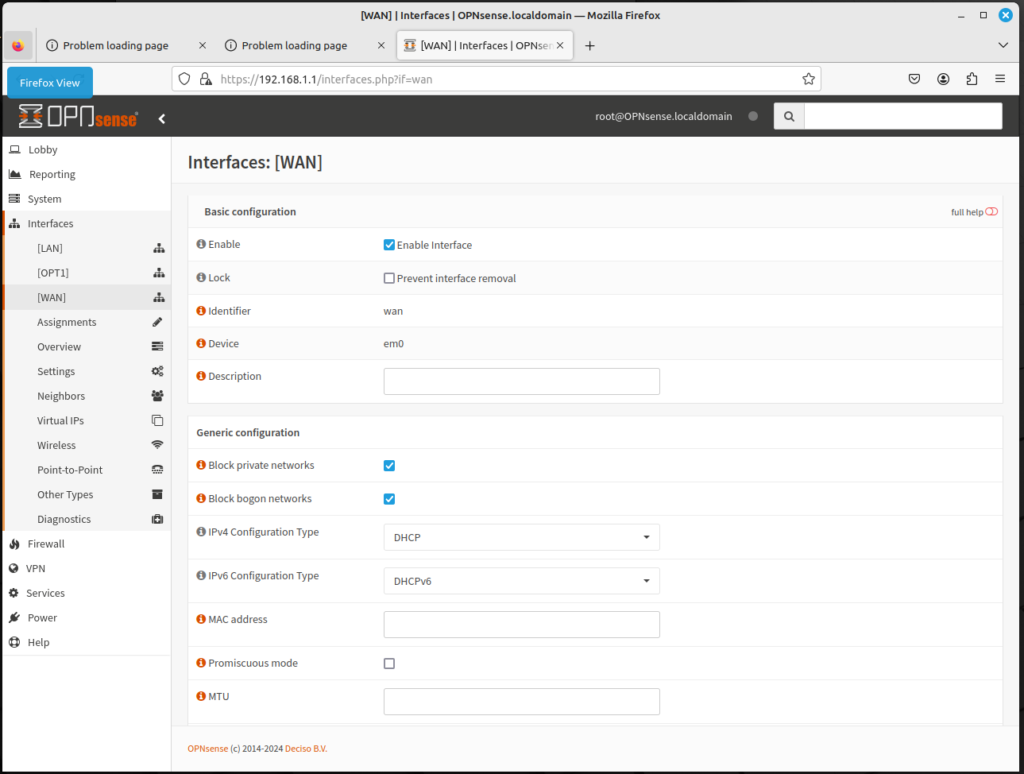
On the WAN interface, there is an option to block private networks and block bogon networks. We should address both these issues.

  • Private networks, also known as RFC 1918 addresses, are blocks of network IP addresses reserved for private use. These addresses are commonly used behind a firewall to allow a single public IP address to be shared with multiple devices using Network Address Translation (NAT). As a general rule, it is good practice to prevent network traffic using private addresses from leaving the firewall via the WAN interface. This avoids unnecessary traffic on the WAN network and provides a security benefit by keeping information about the LAN network behind the firewall. This option should remain checked. There are two circumstances in which this option should not be selected:
    • When your Internet service provider (ISP) assigns private network addresses to their customers
    • When the firewall is behind another firewall or router.
  • Bogon networks are those which should never be seen on the Internet, including reserved and unassigned IP address space; the presence of traffic from these networks can indicate either spoofed traffic or an unused subnet that has been highjacked for malicious use, Normally, bogon networks should be blocked on the WAN, so this option should be checked.

You need to choose the selected type for this interface. For most ISPs, this should be DHCP, as it is the mechanism used to distribute IP addresses. But if your ISP assigned a static IP address, there’s an option for this as well. There are also several different options for configuration type:

  • PPP: Point-to-Point Protocol, which should be the option if your ISP supports it
  • PPoE: Point-to-Point over Ethernet
  • PPTP: Point-to-Point Tunneling Protocol, which some VPNs use
  • L2TP: Layer 2 Tunneling Protocol, another option some VPNs use

There is an option for MAC address. Here you can enter a different MAC address, which

There are also options for MTU (Maximum Transmission Unit) and MSS (Maximum Segment Size). The default for MTU is 1500; the default for MSS is 536 for IPv4 and 1220 for IPv6. Increasing either of these options could optimize speed on your network, but in most cases, you probably should keep these at the default.

There is an option for speed and duplex. Here there is a variety of options, from 1000baseT, 100baseTX, and 10baseT. In most cases, you can leave this at the default value, which will cause the speed and duplex to autoselect.

In the WAN settings, there are options for DHCP client configuration and DHCPv6 client configuration, but for the most part, you can leave these settings unchanged and click on the Next button.

The next interface to configure is the LAN interface. There is also an option to block private networks and block bogon networks. It is generally recommended that these options will not be checked, as the LAN interface is not the interface to the Internet.

Next is the configuration type. Unlike the WAN interface, this should be configured as Static, unless you have a DHCP server upstream, in which case you should use DHCP. Selecting static means that you must manually configure the static IPv4 and IPv6 options. Unless you have reason for having a different address configuration, IPv4 should be designated as 192.168.1.1 and IPv6 should be designated as fd00:1::1/64.

There are also options for MAC address, MTU and MSS. Unless there is a compelling reason to change these options, you should keep these as the default values.

By clicking on the Save button, you will have configured both the LAN and WAN interfaces. Next is configuring the DMZ and configuring VLAN settings, which will be covered in future articles.