Silverstone CMD01-ESA Review

CMD01-ESA Review

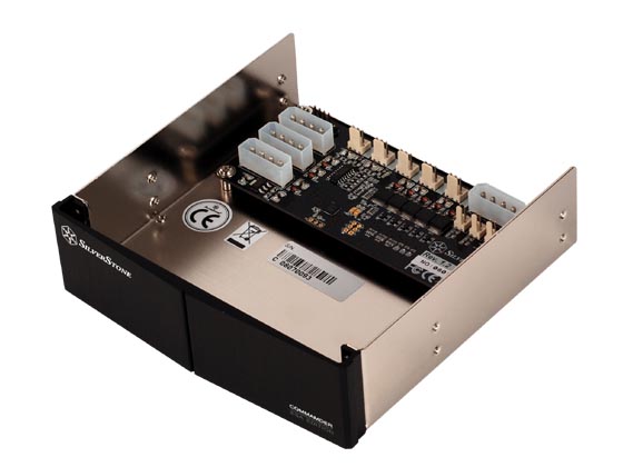
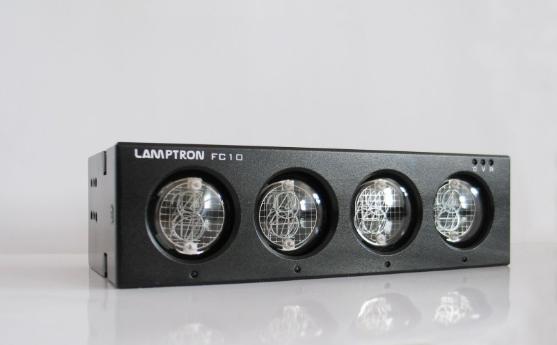
Front view of the CMD01-ESA. Note there are no controls on the front panel; everything is controlled via software.

The Silverstone CMD01 Commander ESA Edition (CMD01-ESA) is a 5-channel, 6 watt per channel automatic fan controller. It fits in a 5.25″ drive bay, and is available in both black and silver. One of the caveats that should be mentioned is that this controller is that ESA stands for “Enthusiast System Architecture”, a royalty-free protocol created by Microsoft, NVIDIA, and Logitech. Therefore you will need a modern NVIDIA motherboard as a base. You can then control the controller, along with various other aspects of the system, with the nTune System Monitor software from NVIDIA. The CMD01 is listed on Silverstone’s website as a legacy product, but it is still selling on Amazon as of this writing. It currently sells on Amazon for $49.99 U.S.D., so it is relatively moderately priced for what it offers.

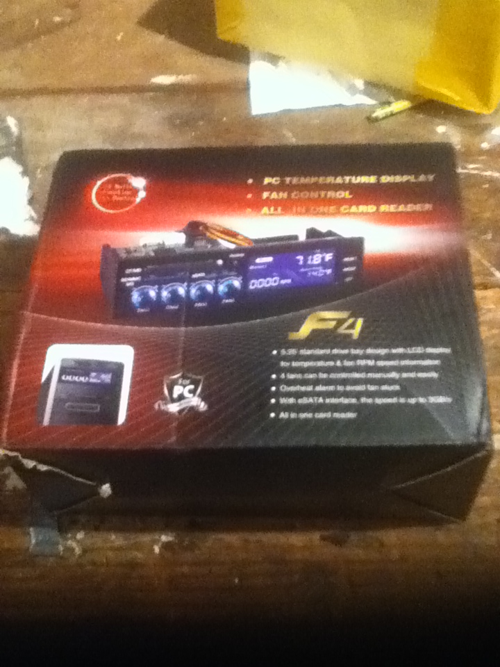
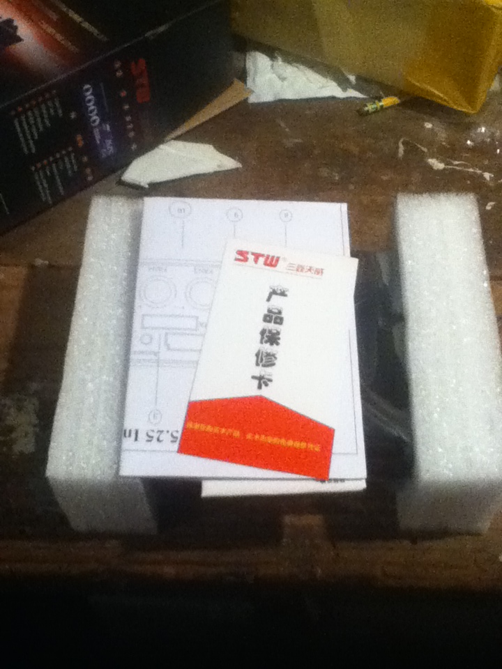
The unit comes in a compact black box. On the front is an image of the controller, and on the back are the controller’s specifications. The unit is placed in a cardboard box inside the outer box, which further protects it. Inside this box, you will find the controller itself, four thermal sensor cables, three fan extension cables, one USB cable (to connect the CMD01 to an internal USB connector on the motherboard), a set of four screws to secure the CMD01 in a 5.25″ drive bay, and a user manual.

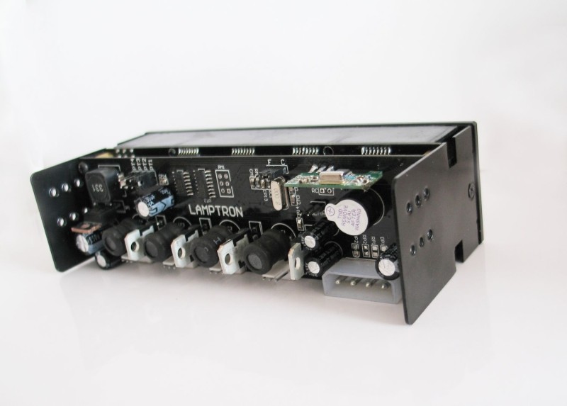
The front of the CMD01 is made of thick aluminum, whlle the rest of the outer frame is made of steel. The use of aluminum on the front gives the unit a high-quality look and feel, or at least a higher-quality look than it would have if it were made of plastic. The PCB inside the unit is black and has a clean, elegant design. Connectors are grouped; the lighting unit connectors are on the left side of the PCB, and the fan connectors are lined up on the top. The four thermal sensors are pluged in beneath the Molex 4-pin power connector, and all the connectors are labeled. There are two integrated circuit chips on the PCB: the SILABS F321 (part of the USB), and the ULN2003AG (for power distribution).

Installation of the CMD01-ESA is very easy. It installs into any 5.25″ drive bay. Once the unit is placed in the drive bay, you just connect the fan cables and place the thermal sensors where you want them to be. The fan cables, however, may not be long enough to put the fans everywhere you may want to place them, especially in larger cases, so you may have to provide your own extension cables. Then connect the USB cable to the motherboard (note that the USB cable is a 4-pin; the typical USB connector on a motherboard is 9 pins). Finally, connect the PSU to the 4-pin Molex power connector on the CMD01. The four thermal sensors can be placed in your computer wherever you want the temperature to be monitored (e.g. memory, hard drives, etc.).

CMD01-ESA Review

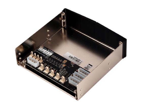
Rear view of the CMD01-ESA.

Once hardware installation is complete, you probably want to turn on the PC, and make sure the CMD01-ESA displays a green LED and that all the fans are running. To use this controller, you must now download the nTune System Monitor from NVIDIA and install it under Windows. The software runs under Windows XP, Vista, and Windows 7 (but apparently not Windows 8). The nTune System Monitor uses ESA (Enthusiast System Architecture), an attempt by NVIDIA to define a standard based on the USB-HID protocol (a protocol used mostly for USB mouses and keyboards). This allows for drastically reduced costs, as there is no need for a dedicated driver, although the use of ESA requires an ESA-compliant motherboard. ESA also introduces monitoring of devices such as PSUs and watercoolers, devices that hitherto could not be monitored from software.

ESA is implemented in software through two programs: NVIDIA System Monitor (to track monitoring data), and NVIDIA Control Panel (to control devices). You will need an NVIDIA chipset-based motherboard to enable all features of these two programs.

If the Silverstone Commander is installed, a case icon symbol should be visible when the nForce System Monitor is run. Clicking on the icon will give you access to up to four fans and the four temperature sensors. You can easily control the speed of the fans, but you cannot control CCFL lights through the System Monitor. The NVIDIA Control panel offers the controls to change the fan speed from 0% to 100%, and to set the lamp colors. You can also define your own rules via the profile tab and assign different fan speeds to different temperatures. As an added bonus, ESA is being adopted by third-party utilities such as HWMonitor, and, as a result, HWMonitor is able to report monitoring data for many ESA devices, including the CMD01-ESA, even if the chipset of your motherboard is not an NVIDIA chipset.

The CMD01-ESA is a solid, moderately-priced fan controller that offers a much more granular level of monitoring and control than most fan controllers. Its main drawbacks, in my opinion, are the fact that it requires a motherboard with an NVIDIA chipset for all the features to work. Also, you cannot control the lighting accents with the software, and the cables are not long enough to reach everywhere in the case. Another complaint is that the power output is only 6 watts per channel, which is rather puny for the price, although it should be enough for most users. Moreover, this is a legacy product, so support for this product may be minimal at best. Still, if you have an NVIDIA chipset that supports ESA, and you don’t mind having to use software to use a fan controller, you could do worse than the CMD01-ESA.

CMD01-ESA Specifications:

Model No.: SST-CMD01B-ESA (Black)
SST-CMD01S-ESA (Silver)
Color: Black, Silver
Material: Aluminum front panel, steel body
Power requirement: +12V
Max fan power: 5 channels, 0.5A per channel
Operating system support: Windows XP, XP-64, Vista, Vista-64, Windows 7
Application: 5.25” drive bay, works with ESA motherboard
Connectors: 3 x 4pin peripheral connectors (300mm)
1 x USB connector (600mm)
4 x thermal sensors (600mm)
Interface: USB 2.0
Fan control function: Adjustable speed or thermal control by NVIDIA control panel
Max lamp power: 3 channels, 0.8A per channel
Lamp control function: On/off function control by NVIDIA control panel
Thermal sensor & range: 4 sensors, 0°C ~ 90°C
Controller Board Dimension: 130mm (W) x 35mm (H) x 55mm (D)
Dimension: 158mm (W) x 42mm (H) x 145mm (D)
weight: 0.8kg

External Links:

Silverstone’s product page for the CMD01-ESA

Enthusiast System Architecture on Wikipedia

STW-ICR-022: First Impressions

Introduction

STW-ICR-022

The outer box of the STW-ICR-022.

I recently came across an inexpensive fan controller on eBay, so I thought I would buy it and share some of my thoughts on installation. The controller is made by Sunshine Tipway Electronic Technology Co., Ltd. (STW), a Hong Kong-based company that manufactures computer accessories, and seems to be focused heavily on fan controllers. You can find out more about their products at the company’s website.

Unboxing

The controller I purchased was the STW-ICR-022, a combination fan controller/card reader with an eSATA interface. The box displays a picture of the controller with a list of some of its features:

  • 5.25″ standard drive bay design with LCD display for temperature & fan RPM speed information
  • 4 fans can be controlled manually and easily
  • Overheat alarm to avoid fan stuck
  • With eSATA interface, the speed is up to 3GB/s
  • All in one card reader
STW-ICR-022

The fan controller and instructions.

I presume the list includes poorly translated English (hence, “easily” instead of “automatically”, and “to avoid fan stuck”). The other side of the box shows the same two photos of the controller, but is written in Chinese. Inside the box, the controller and accessories is contained in an anti-static bag in between two pieces of polystyrene, as shown. Included is a small handout written in Chinese, an instruction manual (also in Chiense), and a big sheet of paper that is the installation guide (in English). Also included are some screws and adhesive tape for the thermal probes in a separate ziploc bag.

Installation of the STW-ICR-022

The fan cables and thermal probes are already connected to the controller. The fan cables can easily be removed to cut down on clutter inside the case if you have fewer than four fans to control. The thermal probes, however, are covered with hot glue, so you’ll have to remove that first if you want to unplug any of the temperature sensors. Installation is easy with the included screws. You will probably want to wait until all the fans are in place and plugged in before screwing in the controller, since the fan headers can easily become unplugged.

STW-ICR-022

The operating instructions (yes, they are in Chinese).

In my case, I hooked up three fans to the controller: [1] the CPU fan; [2] the rear exhaust fan, and [3] an old CPU fan which I put in the front in order to dissipate some of the heat created by the hard drives. Once the fans were connected, Those who have 4-pin PWM fans will be happy to know that the cables accommodate both 3-pin and 4-pin fans. it was a relatively easy matter to put the thermal probes in the appropriate places. The sticky tape included with the controller proved inadequate, so I used electrical tape. There is also a USB cable for the card reader, and a SATA cable for the eSATA interface.

Testing: The STW-ICR-022 in Action

With the installation complete, I powered up the system. The display cycles through displaying the fan speed and temperature for each channel. There are three buttons on the front panel: “RESET”, “MODE”, and “C/F”. “RESET” is presumably to restore factory settings, although when I pressed this button, it did not seem to have any effect on the settings. “MODE” toggles between manual and automatic mode, and “C/F” toggles between Celsius and Fahrenheit in the temperature display. There are alarms indicating when a fan stops (or is disconnected) and when the temperature of one of the thermal sensors reaches the alarm temperature. The alarm temperature is set by holding down the “MODE” button until the display starts blinking. Pressing the “MODE” again while the display is blinking allows you to select other channels. Pressing the “C/F” button while the display is blinking increases the alarm temperature (the threshold at which the alarm will sound). Once you reach 190° F, the temperature wraps back around to 104° F. Pressing the “MODE” button repeatedly (one cycle through all the channels) will take the controller out of temperature alarm setting mode.

STW-ICR-022

Close-up of the thermal sensors.

I disconnected one of the fans, and sure enough, the fan alarm activated. The controller started beeping, although it stopped beeping after about two minutes. As for the temperature alarm, the controller started beeping when the target temperature was reached. But the speed of the fan on that channel did not increase, even when the controller was in automatic mode, which is what I would have expected to happen. In fact, I’m not even sure what the point of toggling between manual and automatic mode is, since there does not seem to be a way to invoke automatic fan control. Also, the temperature readings seem to fluctuate quite a bit, and while they generally seem to be accurate, the fluctuations are a cause for concern.

I have not tested the card reader or eSATA interface yet, so I cannot evaluate their effectiveness. The specifications on the box, however, report that the throughput on the eSATA interface is “up to 3 GB/s”, which sounds right for eSATA. I have two additional points of contention with this controller. First, the box says “Maximum power output < 10W”. I’m not sure if that means less than 10W per channel or 10W total. If it is 10 watts per channel, this controller will be more than adequate; 10W total, however, makes for a pretty puny controller. Second, there does not seem to be any way of switching off the LED backlight that illuminates the case. This is a small point, but the LEDs generate a good deal of light pollution in a darkened room.

Conclusion

I will post a second article after I have done some more detailed testing on the controller. As of now, however, I cannot endorse this product, for the following reasons: [1] lack of instructions in English; [2] even though the unit is sold as a manual/automatic fan controller, there doesn’t seem to be any way to control the fans automatically. Admittedly, my appraisal of this product is influenced heavily by the lack of instructions in English; if there were clearly-written English instructions (there is a single sheet of paper written in English that explains how to install the unit, and what the buttons and display do), the full functionality of the unit might become obvious. Such instructions were not furnished, however, so I had to try to figure it out myself. If anyone has any experience with this product, and cares to fill in some of the gaps in my knowledge, I would love to hear it.

Specifications:

Dimensions: 14.9 x 8.8 x 2.4 cm
Installation location: 5.25″ drive bay
Power interface: Big 4-pin connector
Fan connector: 3-pin/4-pin
Material: Aluminum-magnesium alloy
Controlled fan: 4 fans
Cable length: 60.0 cm
Maximum power output: < 10W
Contents: 4 screws, manual


Lamptron FC10 Review

Lamptron FC10 Review

Front view of the Lamptron FC10.

A fan controller that combines aesthetics and functionality, the FC10 offers up to 30 watts per channel (with a total of 4 channels). It also features a remote control (for controlling the display), and the special edition has interchangeable faceplates. It fits into a single 5.25″ drive bay. The retail price is $69.99.

The product ships with a box that includes an instruction manual, 4 temperature sensors, 4 sleeved 3-pin extensions, 1 jumper, 4 screws, the remote control, and the fan controller itself. The cables are fully-braided, and should be more durable overall.

The remote control has 7 buttons: an “Open” button, a “Close” button, a “M” button, a “<<” button, a “>>” button, and a “+” and “-” button. Open and Close are to turn the display on and off, while the “M” button stands for mode and is used to switch between display modes: temperature, voltage, and RPM. The double arrows (“<<” and “>>”) are for channel selection, and the “+” and “-” buttons are for increasing and decreasing the voltage in 1 volt increments/decrements. Unfortunately, the only way of controlling the fans is through the remote control, so if the remote control battery dies, there is no way of controlling the fans until you get a new battery. Also if you lose the remote control, you are out of luck. In addition, the remote itself is somewhat thin and flimsy feeling.

The display uses real Nixie tubes: glass tubes filled with gas that give off an orange glow when current passes through them. These tubes were primarily used for scientific equipment between the 1950s and early 1970s, and give the controller a distinctly retro feel. Under each Nixie tube is an LED that indicates which fan/probe is under control/monitoring. There are also three LEDs indicating which is being displayed: temperature, voltage, and RPM.

Lamptron FC10 Review

Back view of the Lamptron FC10.

The back of the controller has all the different connectors on a PCB (there are two PCBs: one for the connectors, and the other for the Nixie tubes). In the top left corner, there are 8-pin connectors for the four temperature probes (PT1-PT4). On the right is a 3-pin connector with a jumper that allows the user to select the temperature unit (Fahrenheit or Celsius). Next to it is the remote received with a wired antenna. Under it is a 2-pin connector with a jumper to enable or disable the speaker. At the bottom right is the 4-pin Molex connector. The rest of the bottom of the first circuit board had the four 3-pin fan connectors.

The controller itself is reliable; the input and output voltages no not fluctuate by much, even when multiple fans are connected to it, and the temperature sensors are quite accurate.

The FC10 is somewhat pricey (list price is $69.99, but often sells for more), and the fact that it can only be operated via remote control will be a deal-breaker for some. Still, it is certainly a unique, stylish product, and those who like the look of the Nixie tubes might consider this controller.

Lamptron FC10 Specifications:

Dimension:  148.5mm x 42.5mm x 75mm (5.25″ Bay)
Power Output:  Up to 30 watts per channel
Control Channel:  4 Channels
Panel Color Available:  Brass, Black, White, Black Bench Drawing Metal, Black w/ Brass Trim
DC Input:  3 X +12v (Standard 4 Pin Molex)
DC Output:  0V-12V DC
Fan Connectors:  4 X 3-pin connectors
Recommend PSU wattage:  400w or higher

External Links:

Lamptron’s product page for the FC10